 Electronic Energy
Control, Inc.
Serving the Energy Management
and Scientific Fields since 1978
(937) 349-6000
(800) 842-7714
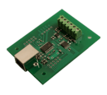
ADC-4U SERIES DESCRIPTION (8, 10 and 12 bit) The ADC-4U series A to D converter provides 4 channels of 8, 10 or 12 bit A to D input. The analog inputs may also be configured for (2) differential inputs. The ADC-4U8, ADC-4U10 and ADC-4U12 connect to any available USB port with operating power supplied from the USB port. The
VA-1 or VA-2 Precision Instrumentation Amp may be used to input lower millivolt signal levels when voltage input levels fall below the 0 to 1 volt minimum (saving the analog input). Up to 136 relays may be controlled or 136 status inputs may be monitored (or combinations) with the addition of the optional expansion ports and the
EX-8M Expansion Module (or EXM-8, EXM-16 or EXM-32 Relay I/O Expansion Modules). The 8 bit inputs (ADC-4U8) provide 256 increments of measurement each. The 10 bit inputs (ADC-4U10) provide 1,024 increments of measurement each. The 12 bit inputs (ADC-4U12) provide 4,096 increments of measurement each. The
EN-D Instrument Case may be used to house the ADC-4U if an enclosure is required. Includes free
event notification software for Smart phones (text message alerts). LabVIEW compatible, includes LabVIEW VI, graphic software example and DLL library. Software interface, driver, data logger software, remote network/Wi-Fi software and source code examples included on CD. The ADC-4U series is also available in WiFi version (ADC4-WIFI), Ethernet version (ADC4-ENET), RS-232 version (ADC4-RS232) or RS-485 version (ADC4-RS485).
ADC-4U Photo and Ordering Information
ADC-4U Technical Reference
ADC-4U SERIES SPECIFICATIONS
SIZE
1.875" by 2.5"
WEIGHT
.5 ounce
INTERFACE
USB
MAXIMUM SAMPLE RATE
(8 bit)...100 samples per second or better
(10 and 12 bit)...50 samples per second or better
INPUT CONFIGURATIONS
software selectable:
(4) single ended analog inputs
(internal reference used) or...
(2) differential analog inputs
SINGLE ENDED VOLTAGE INPUT RANGE
software selectable:
0 to 4 volt internal (default range)
0 to 3.3 volt/0 to 5 volt external or...
user provided (1 analog input used)...
0 to 1 volt up to 0 to 5 volts DC
DIFFERENTIAL VOLTAGE INPUT RANGE
software selectable:
+4 to -4 volts DC (default)
+5 to -5 volts DC
+3.3 to -3.3 volts DC or...
user provided... +1 to -1 volts up to
+5 to -5 volts
OPTIONAL EXPANSION PORTS
(3) add up to 136 relay outputs,
136 status inputs
or combinations using EX-8M, EXM-8,
EXM-16 or EXM-32 expansion modules
OPERATING SYSTEMS
compatible with Windows XP
(service pack 3),
Vista, Windows Server, Windows 7, Windows 8.1 and Windows 10
Windows 11 version available
LabVIEW compatible
OPERATING TEMPERATURE
-40 degrees C to 85 degrees C
POWER REQUIREMENTS
powered from USB connection (5V, 50mA)
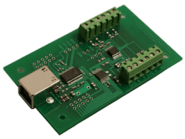
ADC-4DU8 ANALOG TO DIGITAL CONVERTER DESCRIPTION (8 bit)
The ADC-4DU8 A to D converter provides (4) channels of single ended (8 bit) A to D input with an additional channel of Digital to Analog output. The analog inputs may also be configured for up to (3) differential inputs. The ADC-4DU8 connects to any available USB port with operating power supplied from the USB port. The
VA-1 or VA-2 Precision Instrumentation Amp may be used to input lower millivolt signal levels when voltage input levels fall below the 0 to 1.6 volt minimum. Up to 136 relays may be controlled or 136 status inputs may be monitored (or combinations) with the addition of the optional expansion ports and the
EX-8M Expansion Module (or EXM-8, EXM-16 or EXM-32 Relay I/O Expansion Modules). The 8 bit inputs provide 256 increments of measurement each. The
EN-D Instrument Case may be used to house the ADC-4DU8 if an enclosure is required. Includes free
event notification software for Smart phones (text message alerts). LabVIEW compatible, includes LabVIEW VI, graphic software example and DLL library. Software interface, driver, data logger software, remote network/WiFi software and source code examples included on CD. The ADC-4DU8 is also available in WiFi version (ADC4D-8WIFI), Ethernet version (ADC4D-8ENET), RS-232 version (ADC4D-8RS232) or RS-485 version (ADC4D-8RS485).
ADC-4DU8 Technical Reference
ADC-4DU8 SPECIFICATIONS
SIZE
1.875" by 2.5"
WEIGHT
.5 ounce
INTERFACE
USB
MAXIMUM SAMPLE RATE
100 samples per second or better
INPUT CONFIGURATIONS
software selectable:
(4) single ended analog inputs or...
(2) single ended plus (1) differential or...
(3) differential analog inputs
(common ground) or...
(2) differential analog inputs (isolated)
SINGLE ENDED VOLTAGE INPUT RANGE
software selectable:
0 to 5 volts DC (default)
0 to 3.3 volts DC or...
user provided... 0 to 1.6 volts up to
0 to 5 volts DC
ANALOG OUTPUT CHANNELS
(1) 8 bit (256 increments) output range
0 to 5 volt (default)
(or same as analog in reference)
DIFFERENTIAL VOLTAGE INPUT RANGE
software selectable:
+5 to -5 volts DC (default))
+3.3 to -3.3 volts DC or...
user provided... +1.6 to -1.6 volts up to
+5 to -5 volts DC
OPTIONAL EXPANSION PORTS
(3) add up to 136 relay outputs,
136 status inputs or combinations using
EX-8M, EXM-8, EXM-16 or
EXM-32 expansion modules
OPERATING SYSTEMS
compatible with Windows XP
(service pack 3),
Vista, Windows Server, Windows 7, Windows 8.1, Windows 10 and Windows 11
LabVIEW compatible
OPERATING TEMPERATURE
-40 degrees C to 85 degrees C
POWER REQUIREMENTS
powered from USB connection (5V, 50mA)
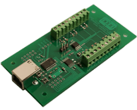
ADC-4U11 and ADC-4U15 DESCRIPTION (11, 12, 15 and 16 bit)
The ADC-4U11 A to D converter provides (4) channels of single ended (11 bit/2,048 increments) A to D input or (2) channels of (12 bit/4,096 increments) differential inputs. The ADC-4U15 A to D converter provides (4) channels of single ended (15 bit/32,768 increments) A to D input or (2) channels of (16 bit/65,536 increments) differential inputs. The ADC-4U11 and ADC-4U15 connect to any available USB port with operating power supplied from the USB port. The
VA-1 or VA-2 Precision Instrumentation Amp may be used to input lower millivolt signal levels when voltage input levels fall below the 0 to 250 millivolt minimum. Up to 136 relays may be controlled or 136 status inputs may be monitored (or combinations) with the addition of the optional expansion ports and the
EX-8M Expansion Module (or EXM-8, EXM-16 or EXM-32 Relay I/O Expansion Modules). The
EN-D Instrument Case may be used to house the ADC-4U if an enclosure is required. Includes free
event notification software for Smart phones (text message alerts). LabVIEW compatible, includes LabVIEW VI, graphic software example and DLL library. Software interface, driver, data logger software, remote network/WiFi software and source code examples included on CD. The ADC-4U11 and ADC-4U15 are also available in WiFi versions (ADC4-15WIFI), Ethernet versions (ADC4-15ENET), RS-232 versions (ADC4-15RS232) or RS-485 versions (ADC4-15RS485).
ADC-4U11 Technical Reference
ADC-4U15 Technical Reference
ADC-4U11 and ADC-4U15 SERIES
SPECIFICATIONS
SIZE
1.875" by 2.5"
WEIGHT
.5 ounce
INTERFACE
USB
MAXIMUM SAMPLE RATE
20 samples per second typical*
*sample rates vary based on cable length and other factors (100 samples per second or better may be achieved)
INPUT CONFIGURATIONS
software selectable:
ADC-4U11:
(4) single ended analog inputs (11 bit
mode) or...
(2) differential analog inputs (12 bit mode)
ADC-4U15:
(4) single ended analog inputs (15 bit
mode) or...
(2) differential analog inputs (16 bit mode)
SINGLE ENDED VOLTAGE INPUT RANGE
software selectable:
0 to 4 volts DC (default)
0 to 5 volts DC
0 to 1 volt DC
0 to 500 millivolt
0 to 250 millivolt
DIFFERENTIAL VOLTAGE INPUT RANGE
software selectable:
+4 to -4 volts DC (default)
+5 to -5 volts DC
+1 to -1 volts DC
+500 millivolt to -500 millivolt
+250 millivolt to -250 millivolt
OPTIONAL EXPANSION PORTS
(3) add up to 136 relay outputs,
136 status inputs
or combinations using EX-8M, EXM-8,
EXM-16 or EXM-32 expansion modules
OPERATING SYSTEMS
compatible with Windows XP
(service pack 3),
Vista, Windows Server, Windows 7, Windows 8.1, Windows 10 and Windows 11
LabVIEW compatible
OPERATING TEMPERATURE
-40 degrees C to 85 degrees C
POWER REQUIREMENTS
powered from USB connection (5V, 50mA)
ADC-8U SERIES DESCRIPTION (8, 10 and 12 bit)
The ADC-8U series A to D converter provides 8 channels of 8, 10 or 12 bit A to D input. The analog inputs may also be configured for (2) differential inputs. The ADC-8U8, ADC-8U10 and ADC-8U12 connect to any available USB port with operating power supplied from the USB port. The
VA-1 or VA-2 Precision Instrumentation Amp may be used to input lower millivolt signal levels when voltage input levels fall below the 0 to 1 volt minimum (saving the analog input). Up to 136 relays may be controlled or 136 status inputs may be monitored (or combinations) with the addition of the optional expansion ports and the
EX-8M Expansion Module (or EXM-8, EXM-16 or EXM-32 Relay I/O Expansion Modules). The 8 bit inputs (ADC-8U8) provide 256 increments of measurement each. The 10 bit inputs (ADC-8U10) provide 1,024 increments of measurement each. The 12 bit inputs (ADC-8U12) provide 4,096 increments of measurement each. The
EN-D Instrument Case may be used to house the ADC-8U if an enclosure is required. Includes free
event notification software for Smart phones (text message alerts). LabVIEW compatible, includes LabVIEW VI, graphic software example and DLL library. Software interface, driver, data logger software, remote network/WiFi software and source code examples included on CD. The ADC-8U series is also available in WiFi version (ADC8-WIFI), Ethernet version (ADC8-ENET), RS-232 version (ADC8-RS232) or RS-485 version (ADC8-RS485).
ADC-8U Technical Reference
ADC-8U SERIES SPECIFICATIONS
SIZE
1.875" by 3.125"
WEIGHT
.5 ounce
INTERFACE
USB
MAXIMUM SAMPLE RATE
(8 bit)...100 samples per second or better
(10 and 12 bit)...50 samples per second or better
INPUT CONFIGURATIONS
software selectable:
(8) single ended analog inputs or...
(4) differential analog inputs
SINGLE ENDED VOLTAGE INPUT RANGE
software selectable:
0 to 4 volt internal (default range)
0 to 3.3 volt/0 to 5 volt external or...
user provided... 0 to 1 volt up to
0 to 5 volts DC
DIFFERENTIAL VOLTAGE INPUT RANGE
software selectable:
+4 to -4 volts DC (default)
+5 to -5 volts DC or +3.3 to -3.3 volts DC or...
user provided... +1 to -1 volts up to
+5 to -5 volts
OPTIONAL EXPANSION PORTS
(3) add up to 136 relay outputs,
136 status inputs
or combinations using EX-8M, EXM-8,
EXM-16 or EXM-32 expansion modules
OPERATING SYSTEMS
compatible with Windows XP
(service pack 3),
Vista, Windows Server, Windows 7, Windows 8.1, Windows 10 and Windows 11
LabVIEW compatible
OPERATING TEMPERATURE
-40 degrees C to 85 degrees C
POWER REQUIREMENTS
powered from USB connection (5V, 50mA)
ADC-12U SERIES DESCRIPTION (8, 10 and 12 bit)
The ADC-12U series A to D converter provides 12 channels of 8, 10 or 12 bit A to D input. The analog inputs may also be configured for (6) differential inputs. The ADC-12U8, ADC-12U10 and ADC-12U12 connect to any available USB port with operating power supplied from the USB port. The
VA-1 or VA-2 Precision Instrumentation Amp may be used to input lower millivolt signal levels when voltage input levels fall below the 0 to 1 volt minimum (saving the analog input). Up to 136 relays may be controlled or 136 status inputs may be monitored (or combinations) with the addition of the optional expansion ports and the
EX-8M Expansion Module (or EXM-8, EXM-16 or EXM-32 Relay I/O Expansion Modules). The 8 bit inputs (ADC-12U8) provide 256 increments of measurement each. The 10 bit inputs (ADC-12U10) provide 1,024 increments of measurement each. The 12 bit inputs (ADC-12U12) provide 4,096 increments of measurement each. The
EN-D Instrument Case may be used to house the ADC-12U if an enclosure is required. Includes free
event notification software for Smart phones (text message alerts). LabVIEW compatible, includes LabVIEW VI, graphic software example and DLL library. Software interface, driver, data logger software, remote network/WiFi software and source code examples included on CD. The ADC-12U series is also available in WiFi version (ADC12-WIFI), Ethernet version (ADC12-ENET), RS-232 version (ADC12-RS232) or RS-485 version (ADC12-RS485).
ADC-12U Technical Reference
ADC-12U SERIES SPECIFICATIONS
SIZE
1.875" by 3.75"
WEIGHT
1 ounce
INTERFACE
USB
MAXIMUM SAMPLE RATE
(8 bit)...100 samples per second or better
(10 and 12 bit)...50 samples per second or better
INPUT CONFIGURATIONS
software selectable:
(12) single ended analog inputs or...
(6) differential analog inputs
SINGLE ENDED VOLTAGE INPUT RANGE
software selectable:
0 to 4 volt internal (default range)
0 to 3.3 volt/0 to 5 volt external or...
user provided... 0 to 1 volt up to
0 to 5 volts DC
DIFFERENTIAL VOLTAGE INPUT RANGE
software selectable:
+4 to -4 volts DC (default)
+5 to -5 volts DC or +3.3 to -3.3 volts DC or...
user provided... +1 to -1 volts up to
+5 to -5 volts
OPTIONAL EXPANSION PORTS
(3) add up to 136 relay outputs,
136 status inputs
or combinations using EX-8M, EXM-8,
EXM-16 or EXM-32 expansion modules
OPERATING SYSTEMS
compatible with Windows XP
(service pack 3),
Vista, Windows Server, Windows 7, Windows 8.1, Windows 10 and Windows 11
LabVIEW compatible
OPERATING TEMPERATURE
-40 degrees C to 85 degrees C
POWER REQUIREMENTS
powered from USB connection (5V, 50mA)
ADC-16 DESCRIPTION
The ADC-16 A to D converter provides two separate 8 channel analog input ports (expandable to 48 analog inputs) which allow input of a wide variety of analog information into a conventional PC. Applications include temperature input (requires TE-8 temperature input conversion and sensors) and input of energy usage or electrical demand (requires watt transducer and current transformer). Other uses include input of pressure, light, voltage, weight, potentiometer movement, strain gauges, etc. (minimal external hardware required). The ADC-16 is very useful as a Data Logger or as an Electronic Chart Recorder. The data logging software for Windows which is provided with the ADC-16, allows the user to export data files into Excel or other programs to generate spreadsheets, charts, graphs etc. The ADC-16 may be used in battery management systems to monitor and control battery voltage levels and system operating characteristics. The ADC-16 also has many applications in the home automation field. Connection of a modem will allow these functions to be monitored from a remote site via telephone line (the EX-16 may be used for remote relay control) or use an Internet connection. The A/D output is represented as a single byte number (0 to 255 decimal) with 8 bit resolution or in two byte format (0 to 1023 decimal) with 10 bit resolution. Voltage inputs of 5 millivolts or higher per increment require no additional hardware. The
VA-1 or VA-2 Precision Instrumentation Amp may be used to input lower millivolt signal levels, for input scaling or to input differential signals. Each of the two analog input ports has an adjustable voltage reference input which allows the analog voltage input level to be adjusted. The default level is 0 to 5 volts DC single ended (20 millivolt resolution, 8 bit). The addition of an external voltage reference will allow greater resolution and lower voltage input levels. EXAMPLE: A 1.2 volt reference will provide a voltage input level of 0 to 1.2 volts (5 millivolt resolution, 8 bit). Inputs can be ratio metric or standard volt. The ADC-16 A/D converter provides an output expansion port to control up to 112 relays (using
EX-16 or EX-32 expansion cards) and an input expansion port which allows for expansion to 48 analog inputs or an additional 128 status (digital) inputs (using
AD-16 or ST-32 expansion card). The TE-8 temperature input conversion may be used for temperature input. Includes free
event notification software for Smart phones (text message alerts).
ADC-16 Photo and Ordering Information
ADC-16 Technical Reference
About Resolution... 8, 10 or 12 bit?
ADC-4 A to D CONVERTER...The ADC-4 provides four 12 bit analog inputs with an optional 8 channel port #2 of 8 or 10 bit resolution. The ADC-4 features the Siemens 12 bit A/D converter IC with an on-chip micro controller and memory for auto calibration. Total unadjusted error is plus or minus 1/2 LSB with no missing codes. The ADC-4 is identical to the ADC-16 in physical size and layout, I/O functions and expansion capability and provides both the relay expansion and input expansion ports. Analog port #2 may be converted for temperature input using the TE-8. Port #1 is used for connection of the four 12 bit inputs via a shielded DB-9 connector. The A/D output is represented in two byte format (0 to 4095 decimal) in 4,096 increments. Voltage input range is fixed at 0 to 5 VDC single ended. Use the
VA-1 or VA-2 Precision Instrumentation Amplifier for lower input voltage ranges, input scaling or for differential inputs.
ADC-4 Photo and Ordering Information
FEATURES - Low cost - High reliability - 25 years of proven performance in the energy management field.
- Quality - Industrial grade components... provided by major manufactures including National Semiconductor, Motorola, Harris, Siemens, Burr-Brown, Maxim and other major manufacturers.
- Ideal for use as a Data Logger or Electronic Chart Recorder. Data Logger software is included for use with Windows. The data export files import easily into Excel, Access and other programs.
- Simplified software development using virtually any programming language that supports serial communications, including DOS based GW Basic, Quick Basic, Turbo C, Assembly and all Windows programming languages including Visual Basic 6, Visual Basic .NET, Visual C#/C++, Python, ASP.net and many others. Source code examples provided. No special drivers or handshaking required.
- Serial data I/O...connects to USB, RS-232 serial I/O ports (or optional RS-422, RS-423 or RS-485) - COM1, COM2, COM3, COM4, etc.
- A wide variety of serial cables and custom made serial cables are available for connection to most computers.
- LabVIEW compatible, includes LabVIEW VI, graphic software example and DLL library.
- Includes ADC-16 Data Acquisition Software for Windows (for use with Windows versions 3.0, 3.1, Windows 95/98/2000/ME/XP/Vista and Windows 7, 8 and 10). This software will allow you to display, label, add unit specifier, scale, offset, and log incoming analog information, plus other additional functions. Software is also provided that allow the ADC-16 inputs and/or relays to be controlled or monitored over a network (LAN, WiFi, Internet, etc.).
- Full documentation is provided, including connection diagrams, pin-outs, hardware interfacing and control software examples. A CD is provided with each order with several Windows desktop and Network Apps and control software examples in Basic, QuickBasic, C, Assembly, Visual Basic 6, Visual Basic .NET, Visual C++/C# along with test software for use in all versions of Windows or DOS.
- Full technical support provided.
- Optional RS-422 and RS-485 serial interfaces available (distances to 4,000 feet) or direct Internet connection using the CO-LAN.
- Available in 8, 10 and 12 bit resolution.
- Control up to 112 Relays, input up to 128 Digital Inputs or up to 48 Analog Inputs. All through a single RS-232 connection (using EX-16, ST-32 or AD-16 expansion cards).
SIZE
5" by 7"
WEIGHT
5 ounce
INTERFACE
USB, RS-232, RS-485, WIFI, Ethernet
MAXIMUM SAMPLE RATE
(8 bit)...1700 samples per second
(10 and 12 bit)...850 samples per second
INPUT CONFIGURATIONS
(16) single ended analog inputs
SINGLE ENDED VOLTAGE INPUT RANGE
selectable:
0 to 5 volt (default range) or...
user provided... 0 to 1.2 volt up to
0 to 5 volts DC
BAUD RATE
shunt selectable:
9,600 baud (default)
50 to 19,200 baud
PROTOCOL
selectable:
8 data bits, 1 or 2 stop bits and no parity (default)
EXPANSION PORTS
(1) Relay Expansion Port (add up to 112 relay
outputs using EX-16 or EX-32 Relay Expansion cards)
(1) Input Expansion Port (allowing up to 48 analog inputs using AD-16 or AD-32 Analog Expansion cards) or (128 digital inputs using ST-32 Digital Expansion cards)
OPERATING SYSTEMS
compatible with all Windows operating systems, including XP, Vista, Windows Server, Windows 7, Windows 8.1, Windows 10 and Windows 11
Compatible with most other operating systems
LabVIEW compatible
OPERATING TEMPERATURE
-40 degrees C to 85 degrees C
POWER REQUIREMENTS
9VDC to 14VDC, 150mA - 300mA
Designed for continuous 24 hour industrial operation.
Powered from any power supply with a voltage output of 9 to 14 volts DC (specify PS-GP-1 wall adapter for single ADC-16).
Analog input connections use a standard 10 contact ribbon cable header socket (.1" centers). A terminal block is provided for power supply and serial I/O connections.
The ADC-16 serial interface meets or exceeds the EIA standard for RS-232C data communications.
Rack mountable with other 5" by 7" cards using the CH series card holder racks.
More detailed information is provided with the ADC-16 documentation.
ADC-4 and ADC-16 Accessories
ADC-16 TEMPERATURE INTERFACE
The ADC-16 Temperature Interface has proven to be an extremely reliable industrial grade temperature interface for connection to RS-232, RS-422, RS-485 or USB. It's low cost and proven performance make it the ideal choice for a wide variety of temperature monitoring applications and is for use with all types of computers which provide an RS-232, RS-422, RS-485 or USB connection.
The following temperature interface products are available:
ADC-8/E Analog to Digital Converter...(provides 8 temperature inputs)*
ADC-16/E/F Analog to Digital Converter...(provides 16 temperature inputs)*
ADC-16/E/F with the AD-16/E/F Analog Expansion Card...(provides 32 temperature inputs)*
ADC-16/E/F with the AD-32/E2/F2 Analog Expansion Card...(provides 48 temperature inputs)*
ADC-16/E/F with the AD-32/E2/F2 Analog Expansion Card and PS-4 Port Selector...(provides 192 temperature inputs)*
*the above products are available with an extended temperature range by adding the 10 bit /G and /H options and/or extended range sensors (see below). The E and F options for the ADC-16 and AD-16 specify that the TE-8 temperature conversion is added in groups of 8 temperature inputs. The E option indicates that the TE-8 temperature input conversion is added to the first 8 channels on the A/D card. The F option indicates that the TE-8 temperature input conversion is added to the second 8 channels on the A/D card.
The TE-8 temperature input conversion provides (8) temperature sensing inputs (with temperature sensors) for use with the
ADC-8, ADC-16 Analog to Digital Converter the
ADC-4 Analog to Digital Converter or the
AD-16 Analog Expansion Card. A terminal block is provided for connections to the temperature sensors using a single twisted pair wire. The temperature sensors may be located up to several thousand feet from the TE-8. The TE-8 connects directly to the analog input port with the ribbon cable provided (four TE-8's will provide 32 temperature inputs with an AD-16 expansion card). Includes (8) precision temperature sensors, (8) trimmer potentiometers (for manual calibration, but not required), resistors, capacitors and voltage reference (if the TE-8 is purchased as a kit, the components must be installed on the ADC-16 or AD-16 cards). The temperature sensors are linear temperature sensing IC's supplied in a TO-92 plastic package. The ADC-16 or AD-16/32 may be ordered with the TE-8 installed by adding the suffix /E or /F (see options) or the ADC-16 may be shipped back to us for installation of the TE-8 at no charge. Temperature range is -40 degrees F to 146 degrees F (-40C to 64C) when used with 8 bit converters or -40 degrees F to 212 degrees F (-40C to 100C) when used with 10 or 12 bit converters. Extended range sensors are also available with a temperature range of -67 degrees F to 302 degrees F (-55C to 150C). Accurate to 1 degree F over the entire temperature range. Includes technical reference, software examples and ADC-16 Data Acquisition Software for Windows which allows you to label, display temperatures, log temperatures and perform other functions (for use with all Windows versions including XP, Vista, Windows 7, 8.1, Windows 10 and Windows 11). Software is also provided that allow the temperature inputs and/or relays to be controlled or monitored over a network (LAN, Internet, etc.).TE-8 ribbon cable length is 15". Dimensions are 1" by 3".
Options for the ADC-4, ADC-8 and ADC-16 may be ordered by adding the proper suffix. The following options may be ordered for the Analog to Digital Converters:
/A422 or /A485 OPTION: The serial I/O is configured for the RS-422 or RS-485 interface, allowing up to a 4,000 foot distance between the PC and ADC-16 (for use with the ADC-4, ADC-8 and ADC-16).
/E OPTION: Port #1 is configured for temperature input (-40 degrees to 146 degrees F) using the TE-8 temperature input conversion (for use with the ADC-8, ADC-16 and AD-16). Includes 8 temperature sensors, 8 trimmers and terminal block.
/F OPTION: Port #2 is configured for temperature input (same as above, for use with the ADC-4/I, ADC-16 and AD-16).
/G OPTION: Port #1 is configured for 10 bit resolution (for use with the ADC-8, ADC-16 and AD-16). 10 bit resolution will allow you to have up to 1,024 increments in the range of measurement.
/H OPTION: Port #2 is configured for 10 bit resolution (for use with the ADC-4/I, ADC-16 and AD-16).
/I OPTION: Optional port #2, 8 channel analog input port for use with ADC-4.
/T OPTION: A TransZorb with self resetting Polyfuse is installed.
/Z OPTION: This option is for use with customized hardware.
PLEASE NOTE: The ADC-4, ADC-8 and ADC-16 require a power supply, connecter cable and terminal block to function. Select the power supply and terminal block for your application and the proper cable for your computer. The EX-16, AD-16 and ST-32 expansion cards require the RC-20 ribbon connecter (sold separately) for connection to the A/D converter.
To order the standard ADC-16 analog to digital converter, specify part number ADC-16. The standard ADC-16 will be supplied with an RS-232 serial interface.
To order any of the above options, add the proper suffix to the part number. Any number of options may be included by adding the proper suffix to the part number.
EXAMPLE:
use ADC-8/E ... to order the ADC-8 with port #1 configured for temperature input.
use ADC-4/A/I ... to order the ADC-4 with RS-422 and the optional 8 bit port #2.
use ADC-16/A/E/F ... to order RS-422 with ports #1 and #2 configured for temperature input.
ADC-T SERIES USB TEMPERATURE INTERFACE DESCRIPTION
The ADC-T series temperature interface allows up to 52 temperature sensors (included) to be connected via any available computer USB port. Up to 136 relays may be controlled or 136 status inputs may be monitored (or combinations) with the addition of the optional expansion ports and the
EX-8M Expansion Module (or EXM-8, EXM-16 or EXM-32 Relay I/O Expansion Modules). Standard resolution provides 1 degree temperature increments or the optional extended resolution provides quarter degree increments. The
EN-D Instrument Case may be used to house the ADC-T if an enclosure is required. LabVIEW compatible, includes LabVIEW VI, graphic software example and DLL library. Software interface, driver, temperature control software, data logger software, remote network/Wi-Fi software and source code examples included on CD.
The ADC-T series is also available with 16, 20, 28, 36, 44 or 52 temperature inputs - contact EECI support for more info.
ADC-T SERIES SPECIFICATIONS
SIZE
1.875" by 2.5"
WEIGHT
.5 ounce
INTERFACE
USB
MAXIMUM SAMPLE RATE
50 samples per second or better
INPUT CONFIGURATIONS
(4) temperature inputs (ADC-T4)
(8) temperature inputs (ADC-T8)
(12) temperature inputs (ADC-T12)
STANDARD TEMPERATURE INPUT RANGE
-40F to 212F (-40C to 100C)
OPTIONAL EXTENDED INPUT RANGE
TEMPERATURE SENSORS
-67F to 302F (-55C to 150C)
OPTIONAL EXPANSION PORTS
(3) add up to 136 relay outputs, 136 status inputs or combinations using EX-8M, EXM-8, EXM-16 or EXM-32 expansion modules
OPERATING SYSTEMS
compatible with Windows XP
(service pack 3),
Vista, Windows Server, Windows 7, Windows 8.1, Windows 10 and Windows 11
LabVIEW compatible
OPERATING TEMPERATURE
-40 degrees C to 85 degrees C
POWER REQUIREMENTS
powered from USB connection (5V, 50mA)
WHAT IS RESOLUTION?
The selection of the analog resolution needed for a particular application is generally based upon the accuracy of the sensor or device connected to the analog input.
An 8 bit analog to digital converter will divide the measurement range into 256 increments.
A 10 bit analog to digital converter will divide the measurement range into 1,024 increments.
An 11 bit analog to digital converter will divide the measurement range into 2,048 increments.
A 12 bit analog to digital converter will divide the measurement range into 4,096 increments.
A 15 bit analog to digital converter will divide the measurement range into 32,768 increments.
A 16 bit analog to digital converter will divide the measurement range into 65,536 increments.
Since most temperature sensors are only accurate to about 1 degree, an 8 bit analog to digital converter will be suitable for measurement of outdoor temperature since the 8 bit converter will allow up to 256 degrees of measurement in one degree increments.
Another example might be a pressure transducer with a working range of 0 to 1000 PSI. An 8 bit converter would present this information in approximately 4 PSI increments... 0 PSI, 4 PSI, 8 PSI, 12 PSI, etc. (1000 divided by 256 equals about 4 PSI). A 10 bit converter will present this information in about 1 PSI increments... 0 PSI, 1 PSI, 2 PSI, 3 PSI, etc. A 12 bit converter will present this information in about quarter PSI increments.
EECI Home Page
Last revision 10-16-2022....URL: https://www.eeci.com
For information, please contact our web master at.... webmanager@eeci.com
EECI is a registered trademark of Electronic Energy Control, Inc.
Copyright ©1996 - 2024 Electronic Energy Control, Inc.
EECI® Control System Technology
All Rights Reserved
Document End