
 Electronic Energy
Control, Inc.
Serving the Energy Management
and Scientific Fields since 1978
(937) 349-6000
(800) 842-7714
DIGITAL TO ANALOG CONVERTERS
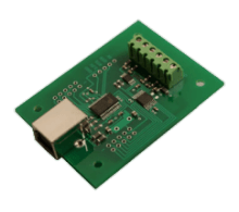
DAC-4U SERIES DESCRIPTION (10 and 12 bit) The DAC-4U series D to A converters provide 4 channels of 10, 12 or 16 bit D to A output. The DAC-4U10, DAC-4U12 or DAC-4U16 connect to any available USB port with operating power supplied from the USB port. Up to 136 relays may be controlled or 136 status inputs may be monitored (or combinations) with the addition of the optional expansion ports and the
EX-8M Expansion Module (or
EXM-16 or EXM-32 Relay I/O Expansion Modules). The DAC-4U10 provides four channels of 10 bit (1,024 increments) of voltage output level. The DAC-4U12 provides four channels of 12 bit (4,096 increments) of output level. The DAC-4U16 provides four channels of 16 bit (65,536 increments) of output level.The
EN-D Instrument Case may be used to house the DAC-4U if an enclosure is required. Includes free
event notification software for Smart phones (text message alerts). LabVIEW compatible, includes LabVIEW VI, graphic software example and DLL library. Software interface, driver, data logger software, remote network/Wi-Fi software and source code examples included on CD. The DAC-4U series is also available in WiFi version (DAC4-WIFI), Ethernet version (DAC4-ENET), RS-232 version (DAC4-RS232) or RS-485 version (DAC4-RS485).
DAC-4U Ordering Information
DAC-4U Technical Reference
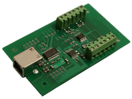
DAC-8U SERIES DESCRIPTION (8, 10 and 12 bit)
The DAC-8U series D to A converters provide 8 channels of 8, 10, 12 or 16 bit D to A output. The DAC-8U8, DAC-8U10, DAC-8U12 and DAC-8U16 connect to any available USB port with operating power supplied from the USB port. Up to 136 relays may be controlled or 136 status inputs may be monitored (or combinations) with the addition of the optional expansion ports and the
EX-8M Expansion Module (or
EXM-16 or EXM-32 Relay I/O Expansion Modules). The DAC-8U8 provides eight channels of 8 bit (256 increments) of voltage output level. The DAC-8U10 provides eight channels of 10 bit (1,024 increments) of voltage output level. The DAC-8U12 provides eight channels of 12 bit (4,096 increments) of voltage output level. The DAC-8U16 provides eight channels of 16 bit (65,536 increments) of voltage output level. The
EN-D Instrument Case may be used to house the DAC-8U if an enclosure is required. Includes free
event notification software for Smart phones (text message alerts). LabVIEW compatible, includes LabVIEW VI, graphic software example and DLL library. Software interface, driver, data logger software, remote network/WiFi software and source code examples included on CD. The DAC-8U series is also available in WiFi version (DAC8-WIFI), Ethernet version (DAC8-ENET), RS-232 version (DAC8-RS232) or RS-485 version (DAC8-RS485).
DAC-8U Technical Reference
DAC-4U and DAC-8U SPECIFICATIONS
SIZE
DAC-4U 1.875" by 2.5"
DAC-8U 1.875" by 3.125"
WEIGHT
.5 ounce
INTERFACE
USB
MAXIMUM UPDATE RATE
(8 bit)...100 updates per second or better
(10 and 12 bit)...50 updates per second or better
OUTPUT CONFIGURATIONS
(4) single ended analog outputs (DAC-4U)
(8) single ended analog outputs (DAC-8U)
REFERENCE VOLTAGE INPUT
selectable:
0 to 3.3 volt or...
0 to 5 volt (default range) or...
user provided... 0 to 1 volt
up to 0 to 5 volts DC
VOLTAGE OUTPUT RESOLUTION
8 bit... 256 increments
10 bit... 1,024 increments
12 bit... 4,096 increments
OPTIONAL EXPANSION PORTS
(3) add up to 136 relay outputs,
136 status inputs
or combinations using EX-8M, EXM-16,
or EXM-32 expansion modules
OPERATING SYSTEMS
compatible with Windows XP
(service pack 3),
Vista, Windows Server, Windows 7, Windows 8.1, Windows 10 and Windows 11
LabVIEW compatible
OPERATING TEMPERATURE
-40 degrees C to 85 degrees C
POWER REQUIREMENTS
powered from USB connection (5V, 50mA)
DAC-1U16 DIGITAL TO ANALOG CONVERTER... The DAC-1U16 is a single channel, 16 bit D to A converter which has an adjustable output range from 0 to .01 volts thru 0 to 5.5 volts (0 to 4.096 volts typical). Relative accuracies are better than plus or minus one tenth of a percent. The DAC-1U16 provides outstanding linearity with zero level output current of less than 4 micro-amps. This 16 bit converter provides 65,536 increments of output voltage. Typical applications include variable air damper control, blower and motor speed control, light level control, audio sound level control, motion control and hundreds of other applications. A terminal block is provided for connections to the analog output (and analog output sense input if required). Available with high precision voltage reference pre-installed. Allows for (0 to 1.2v), (0 to 2.048v), (0 to 2.5v), (0 to 3v) or (0 to 4.096v) output ranges (please contact technical support for more information). Up to 136 relays may be controlled or 136 status inputs may be monitored (or combinations) with the addition of the optional expansion ports and the
EX-8M Expansion Module (or
EXM-16 or EXM-32 Relay I/O Expansion Modules). The
EN-D Instrument Case may be used to house the DAC-1U16 if an enclosure is required. LabVIEW compatible, includes LabVIEW VI, graphic software example and DLL library. Includes technical reference, user interface, software examples and Windows device driver. Powered from USB (20ma). The DAC-1U16 and DAC-2U16 are also available in WiFi version (DAC2-WIFI), Ethernet version (DAC2-ENET), RS-232 version (DAC2-RS232) or RS-485 version (DAC2-RS485). Dimensions are 1.875" by 2.5".
DAC-1U16/DAC-2U16 Ordering Information
DAC-2U16 DIGITAL TO ANALOG CONVERTER... The DAC-2U16 is a 16 bit, two channel version of the DAC-1U16 described above. Includes technical reference, user interface, software examples and Windows device driver. Powered from USB (20ma). Dimensions are 1.875" by 2.5".
DA-1 DIGITAL TO ANALOG CONVERTER... The DA-1 is a single channel, 8 bit, D to A converter which has an adjustable output range from 0 to 1.25 volts thru 0 to 6 volts (0 to 5 volts typical). The DA-1 connects directly to any of the output ports on the AR-16 Relay Interface or the EX-16 Relay Expansion card (requires eight digital outputs). The DA-1 may be connected to other types of digital equipment which will provide eight TTL level outputs for connection to the DA-1. Relative accuracies are better than plus or minus two tenth of a percent. The DA-1 provides outstanding linearity with zero level output current of less than 4 micro-amps. The 8 bit converter provides 256 increments of output voltage. Typical applications include variable air damper control, blower and motor speed control, light level control, audio sound level control, motion control and hundreds of other applications. A terminal block is provided for connections to the power source and analog output. A ribbon cable is provided for connection to the AR-16 or EX-16. The DA-1 and DA-2 are also available with a 0 to 10 volt output range (please contact technical support for more information). Includes technical reference, software examples and test software. Requires an isolated 18 volt power supply, 50 ma (specify PS-12VDC-500 wall adapter). Dimensions are 1.75" by 4.875".
DA-1/DA-2 Ordering Information
DA-2 DIGITAL TO ANALOG CONVERTER... The DA-2 is an 8 bit, two channel version of the DA-1 described above. Two ribbon cables are provided for connection to the AR-16 or EX-16 relay ports (requires sixteen digital outputs). Includes technical reference, software examples and test software. Requires an isolated 18 volt power supply, 100 ma. (specify PS-12VDC-500 wall adapter). Dimensions are 2.125" by 7".
Digital to Analog with A to D
PRECISION INSTRUMENTATION AMPLIFIERS
VA-1 PRECISION INSTRUMENTATION AMPLIFIER...The VA-1 is a high input impedance precision instrumentation amplifier with a typical input impedance of about 1 trillion ohms (minimum 1.0 nA input current required) which utilizes the most recent technology developed by Burr-Brown (one of the foremost leaders in analog design). The VA-1 is configurable for both single-ended and differential inputs. A terminal block is provided for connections to the power source and signal I/O. Requires an isolated 18 volt power supply, 50 ma (specify PS-12VDC-500 wall adapter).
VA-2 PRECISION INSTRUMENTATION AMPLIFIER...The VA-2 is a two channel version of the VA-1. Requires an isolated 18 volt power supply, 100 ma (specify PS-12VDC-500 wall adapter).
VA-4 PRECISION INSTRUMENTATION AMPLIFIER...The VA-4 is a four channel version of the VA-1. Requires an isolated 18 volt power supply, 100 ma (specify PS-12VDC-500 wall adapter).
VA Series Ordering Information
VA-1, VA-2 and VA-4 SPECIFICATIONS
SIZE
(VA-1)... 1.75" by 3.75"
(VA-2)... 1.75" by 5.25"
WEIGHT
(VA-1)... 1 ounce
(VA-2)... 2 ounces
OFFSET VOLTAGE
50 micro-volts (maximum)
DRIFT
0.5 micro-volts per degree C (maximum)
COMMON MODE REJECTION
115 dB (minimum)
INPUT VOLTAGE PROTECTION
to +40 or -40 volts without damage
VOLTAGE OUTPUT RANGE
adjustable:
0 to 5 volts DC (for direct connection to the ADC-4, ADC-4U, ADC-8U and ADC-12U series, ADC-16 and others)
VOLTAGE INPUT RANGE
adjustable:
0 to 1 millivolt through 0 to 5 volts DC
(0 to 100 millivolt typical)
DIFFERENTIAL INPUT RANGE
adjustable:
+1 to -1 millivolt through +5 to -5 volts DC
(+1 to -1 volt typical)
OPERATING TEMPERATURE
-40 degrees C to 85 degrees C
POWER REQUIREMENTS
18 to 24 volts DC (100 ma)
CO-420R PRECISION 4 to 20mA RECEIVER
The CO-420R Precision 4 to 20ma Converter utilizes the most recent technology developed by Burr-Brown (one of the foremost leaders in analog design). The CO-420R will provide an output level of 0 to 5 volts DC for connection directly to any of EECI's Analog to Digital Converters. The CO-420R converter will provide a 0 volt output with 4ma on the input loop and a 5 volt output with 20ma on the input loop along with the corresponding values in the 4 to 20ma range (example: 12ma on the loop will convert to a 2.5 volt DC output on the CO-420R, etc.). A terminal block is provided for connection to the input, output and power source. Other features include high noise immunity (86dB CMR), 0.1 percent overall conversion accuracy, internal sense resistors and + and - 40V common-mode input range. The CO-420 provides a current source for the 4 to 20ma loop. Includes technical reference and applications information. Also available in a 4 channel version (contact EECI support for more information). Size 1.6" by 2.25" (requires PS-24VDC-250 power adapter). Connects to all EECI Analog to Digital Converters to provide USB 4-20mA monitoring, Wifi 4-20mA monitoring (wireless), Ethernet 4-20mA monitoring, RS-232 4-20mA monitoring or RS-485 4-20mA monitoring.
CO-420T PRECISION 4 to 20mA TRANSMITTER
The CO-420T Precision 4 to 20ma Transmitter accepts a 0 to 4.096 volt input and converts to a 4-20mA output. The CO-420T will provide an output level of 4-20mA DC for connection directly to the DAC-4U or DAC-8U. A terminal block is provided for connection to the input, output and power source. Includes technical reference and applications information. Also available in a 4 channel version with isolated 4-20mA outputs (contact EECI support for more information). Size 1.6" by 2.25". Powered from the DAC-4U, DAC-8U, 5 VDC power pack or external power adapter. Connects to all EECI Digital to Analog Converters to provide USB controlled 4-20mA loops, Wifi controlled 4-20mA loops (wireless), Ethernet controlled 4-20mA loops, RS-232 controlled 4-20mA loops or RS-485 controlled 4-20mA loops.
CO-420 Ordering Information
STA-16 STATUS INPUT INTERFACE
The STA-16 Status Input Interface provides two 8 channel status input ports which allow input of on/off status information into a conventional PC for a wide variety of monitoring and signaling applications. Uses include the input of on/off status information of relays, switches, thermostats, security system motion detectors and magnetic switches, smoke detectors, heating and air conditioning equipment, air flow switches, air damper position switches, pressure switches and thousands of other devices. The STA-16 also has many applications in HVAC and home automation. The energy consumption of equipment with a constant load (lighting, resistance heating, hot water heaters, etc.) is easily computed by multiplying the time on by the equipment's KW rating. The STA-16 is ideal for use in logging energy usage or equipment performance and is also well suited for use as a security system logger (to record times doors are opened, motion detectors tripped, alarms or other events). Other uses include the input of 8 or 16 bit binary codes for interfacing to TTL or CMOS level digital signals (allowing connection to counters, parallel data bus lines and other types of digital devices and equipment). The KY-12M Keypad may be connected directly to the STA-16 status input ports for use with security systems, door entry access, remote data entry and other uses. A modem will permit the status inputs to be monitored from a remote site (or use an Internet connection). The status information is obtained by transmitting a single byte port code to the STA-16. The STA-16 then transmits back a single byte code with each bit representing the 8 inputs on that port. The status inputs are turned on by applying a small current (6 ma typical) to the LED inside the opto coupler on the STA-16 (minimum 1.5 volts required, common cathode). Optional AC opto couplers are available which will turn on in both directions, allowing for both common cathode and common anode configurations. The input voltage range defaults to a 6 to 18 volt range with a 1.8 K series resistor to the LED (the STA-16 may be ordered with other resistor values or with no resistors by specifying the /M option). The STA-16 Status Input Interface provides a relay expansion port to control up to 112 relays (using
EX-16 or EX-32 relay expansion cards) and an input expansion port which allows for expansion to 144 status inputs or 32 analog inputs (using
ST-32,
AD-16 or AD-32 expansion cards). An optional Touch Tone input is also available. Includes technical reference, software examples and STA-16 Data Acquisition Software for Windows (for use with all Windows versions including 3.0, 3.1, Windows 95, 98, 2000, ME, XP, Vista, Windows 7, 8.1 and 10). Software is also provided that allow the STA-16 inputs and/or relays to be controlled or monitored over a network (LAN, Internet, etc.).
FEATURES - Low cost - High reliability - 30 years of proven performance in the energy management field.
- Quality - Industrial grade components... provided by major manufactures including National Semiconductor, Motorola, Harris, Siemens, Burr-Brown, Maxim and other major manufacturers.
- Serial data I/O...connects to USB, RS-232 serial I/O ports (or optional RS-422, RS-423 or RS-485) - COM1, COM2, COM3, COM4, etc.
- A wide variety of serial cables and custom made serial cables are available for connection to most computers.
- Simplified software development using virtually any programming language that supports serial communications, including DOS based GW Basic, Quick Basic, Turbo C, Assembly and all Windows programming languages including Visual Basic 6, Visual Basic .NET, Visual C#/C++, Python, ASP.net and many others. Source code examples provided. No special drivers or handshaking required.
- Driver not required. This permits use with all operating systems that support serial communications. Drivers and DLLs are available to simplify software development when requested (please contact EECI support).
- All 16 status inputs are electrically isolated with opto isolators (opto isolators are included).
- Optional Touch Tone input and AC inputs are available.
- Optional RS-422 or RS-485 serial interface available (distances to 4,000 feet) or direct Internet connection using the CO-LAN.
- Available in an 8 channel version.
- Full documentation is provided with the STA-16, including connection diagrams, pin-outs, hardware interfacing and control software examples. A CD is provided with each order with several Windows desktop and Network Apps and control software examples in Basic, QuickBasic, C, Assembly, Visual Basic 6, Visual Basic .NET, Visual C++/C# along with test software for use in all versions of Windows or DOS.
- Full technical support provided from on-staff technical advisers.
- Control up to 112 Relays, input up to 144 Digital Inputs or up to 32 Analog Inputs. All through a single RS-232 connection (using EX-16, ST-32 or AD-16 expansion cards).
The STA-16 may be ordered with an optional touch tone input which decodes all 12 of the standard telephone tones plus 4 additional tones which may be used for control functions. An interrupt output is provided on the STA-16 which may be used in generating an RS-232 interrupt when a tone is detected. A Molex connector (.1" centers) is used for connection to the touch tone input. The touch tone input may be connected directly to a telephone line with the addition of the VC-1 voice coupler. The touch tone input may be used for a variety of applications such as voice mail, telephone call routing, and remote control applications which allow remote input of control functions into a conventional PC from any touch tone telephone.
VC-1 VOICE COUPLER...The VC-1 connects directly to the STA-16 tone input via a Molex connector cable (included). A terminal block is provided for connection to a power source and for the RS-232 I/O interface connection to your PC. This interface allows the PC to monitor for rings and allows the PC to place the telephone off-hook. The VC-1 may share the same RS-232 that is used with the STA-16. Two RJ11 telephone jacks are provided on the VC-1 which are selectable line 1 or line 2. One of the RJ11 jacks is used for connection to the telephone line and the other RJ11 may be used for connection to an additional telephone, modem or other device. The VC-1 also provides voice input and voice output connections which may be used with a sound card. The voice input may be used for providing a message to the calling party, music on hold or other functions. The voice output may be used to record a message from the calling party or for other uses. LED indicator lamps are provided to indicate ring, off-hook and power. Requires a power source (12 to 14 volts DC, 100ma). Dimensions are 2.25" by 4".
KY-12M KEYPAD
The KY-12M keypad is a 12 key keypad with a matrix decoder. The keypad connects to the decoder card via an 18" ribbon cable (provided) and the decoder card connects to the STA-16, ADC-16, ST-32 or AD-16 port via a 14" ribbon cable (provided). The KY-12M requires 4 digital or analog inputs. An interrupt output is provided on the KY-12M which may be used in generating an RS-232 interrupt when a key press is detected. The KY-12M may be ordered with a terminal block in place of the ribbon cable for installation away from the STA-16 or for use with other types of equipment which provide TTL level digital inputs. The KY-12M Keypad may be powered through the ribbon cable by the STA-16 or ADC-16 or may be powered by an external 5 to 12 volt DC power source (50 ma). Size 2.875" by 1.75" (fits in a standard single gang electrical box). Includes software examples, test software, and technical data.
KY-12M Photo
PAC-C STATUS INPUT PACKAGE
The STA-16 status input package is an assembled package which includes the EN-A 7" by 10" plastic enclosure, the STA-16 status input card, (1) RCT-16 terminal block, (1) power supply and (1) connecter cable. The serial cable supplied will be the CC-DB25S unless specified otherwise.
PAC-C Photo
ACCESSORIES FOR USE WITH THE STA-16
AD-16 and AD-32 Analog Expansion Cards
ST-32 Status Expansion Card
EX-16 and EX-32 Relay Expansion Cards
Keypads and Keypad Accessories
VC-1 Voice Coupler
Precision Instrumentation Amplifiers
PS-4 Port Selector
CH series Card Racks
Relay Cards and Relay Driver Cards
Power Relays and Relay Modules
Ribbon Cable to Terminal Block Adapters
Connector Cables and Power Supplies
Serial Interface Cards and Converters
Enclosures and Mounting Hardware
SP-1 Power Protector and TransZorbs
SPECIFICATIONS Designed for continuous 24 hour industrial operation.
Baud rate is selectable (50 to 19,200 baud). Default protocol is 8 data bits, 2 stop bits and no parity. Jumpers may be used to select other protocols. Maximum sampling rate is 1,700 samples per second (eight channels at 19,200 baud).
Use the ST-32 status expansion cards to expand up to 144 status inputs or the AD-16/AD-32 expansion card to add up to 32 analog inputs. Use the EX-16/EX-32 expansion cards to control up to 112 relays. The PS-4 port selector may be used to connect satellite STA-16 interface cards, allowing input of up to 576 status and control of up to 448 relays from a single RS-232.
Powered from any power supply with a voltage output of 9 to 14 volts DC. Requires 300 ma (specify PS-GP-1 wall adapter for single STA-16).
Status input connections use a standard 10 contact ribbon cable header socket (.1" centers). A terminal block is provided for power supply and serial input connections.
Dimensions...5" by 7" (rack mountable with other 5" by 7" cards using the CH series card holder racks).
OPTIONS Options for the STA-16 may be ordered by adding the proper suffix. The following options may be ordered for the STA-16 Status Input Card:
/A422 Option: The STA-16 serial I/O is configured for the RS-422 interface.
/A485 Option: The STA-16 serial I/O is configured for the RS-485 interface.
/D Option: Touch tone input is installed on the STA-16. The touch tone signal is connected using a Molex connecter (located on the top right hand side of the card).
/M Option: Input voltage limiting resistors of a specified value are installed on the STA-16. The desired resistance value should be added to the part number after /M. A part number of STA-16/M0 is used to specify no resistor installed.
/T OPTION: A TransZorb with self resetting Polyfuse is installed.
/Z Option: This option is for use with customized hardware. A 6 digit code will follow the Z suffix to identify the customer and type of modification.
PLEASE NOTE: The STA-16 requires a power supply (PS-GP-1 typical), connecter cable (CC-DB9S typical) and terminal block (RCT-16 typical) to function. Select the proper cable, power supply and terminal block for your application and computer from the associated data sheets. The EX-16, ST-32 and AD-16 expansion cards require a ribbon cable connecter (part number RC-20, sold separately) for connection to the STA-16.
To order the standard STA-16 status input card, specify part number STA-16. The standard STA-16 will be supplied with an RS-232 serial interface.
To order any of the above options, add the proper suffix to the STA-16 part number. Any number of options may be included by adding the proper suffix to the STA-16 part number.
EXAMPLE: use STA-16/D ... to order the STA-16 with the touch tone input
use STA-16/A485 ... to order RS-485
use STA-16/D/M5K ... to order the touch tone input and 5K limiting resistors
PAC-B ANALOG TO DIGITAL PACKAGE
The ADC-16 analog to digital package is an assembled package which includes the EN-A 7" by 10" plastic enclosure, the ADC-16 analog to digital converter, (1) RCT-16 terminal block, (1) power supply and (1) connecter cable. The serial cable supplied will be the CC-DE9S unless specified otherwise.
PAC-B Photo and Ordering Information
EECI Home Page
Last revision 4-03-2025....URL: https://www.eeci.com
For information, please contact our web master at.... webmanager@eeci.com
EECI is a registered trademark of Electronic Energy Control, Inc.
Copyright ©1996 - 2026 Electronic Energy Control, Inc.
EECI® Control System Technology
All Rights Reserved
Document End